-
 Current Sensor Board - Testing
- Date Thu 03 March 2016
- By Jason Jones
- Category current-sensor
- Tags current-sensor buffer current sensor project
For a project introduction, go back to the first post!
Intro
So, if you are already familiar with the project, you know that I was looking for a quick general-purpose current-to-voltage converter with a low-impedance output. I received boards this weekend and was able to solder together the module today. Doesn't look like a million bucks, but works just fine.
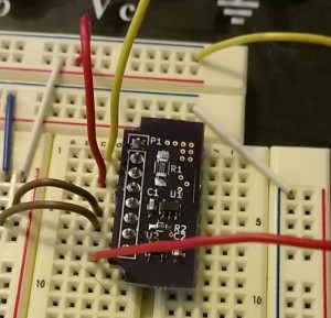
All files may be found on github. There are no patch wires on this version, so files within the master branch should be pretty safe. I may do a release tag at some point to indicate as much.
Module Rating and Gain Settings
When I went to order parts, I realized that I should order parts for a variety of current ranges.
| Rsense | Rgain | Rated Current | Transimpedance |
|---|---|---|---|
| 0.05Ω | 33kΩ | 3.0A | 1.65V/A |
| 0.5Ω | 33kΩ | 300mA | 16.5V/A |
| 4.7Ω | 22kΩ | 30mA | 103.4V/A |
| 47Ω | 22kΩ | 3mA | 1034V/A |
The gain resistor should be set to 33kΩ for 5V devices and 22kΩ for 3.3V devices. This table simply summarizes a few valid configurations that the user might find necessary. If you would like to suggest a combination, leave a comment.
I am choosing the second combination for my initial tests. We will be testing more configurations later! The transimpedance is 16.5V/A and the rating is 0.3A, which should place many small devices within its range.
Testing
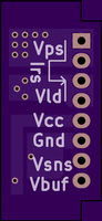
A quick explanation of module functionality is in order. There are two pins dedicated to power supply (Vps) and two pins dedicated to the load (Vld). Current should flow from Vps to Vld. Reverse current will not damage the device, but the sense current will not be accurate either.
Vcc should be the same voltage as your sense circuit. Generally, this will be 3.3V or 5V. This voltage can be anything between 2V and 5.5V.
Vsns is a high-impedance output. The only use for this pin is to add a filter capacitor. In most applications, this pin should be left floating.
Vbuf is the low-impedance, buffered output that is suitable for most ADCs. Vsns and Vbuf should reflect the same voltage at all times.
DC Testing
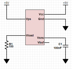
The first and easiest test is to apply a known resistance load to the module and to calculate the current that would flow through that resistor, comparing the calculated current with the measured current. We will apply 5V to Vcc and to the power supply pin (Vps) of the module. Our load will be a nominal 100Ω load. Measuring the resistor with a multimeter actually shows a 98.4Ω load. Measuring the power supply yields a 5.05V PSU. We will use these numbers instead of the nominal values.
5.05V/98.4Ω = 51.32mA
51.32mA * 16.5V/A = 846.8V

At 0A (no resistor load), the voltage is very low, but there is an oscillation visible on the output of the opamp. This oscillation is also visible on the sensor output and is NOT present on the power supply voltage. As a result, I can only conclude that the oscillation is caused by the internals of the INA139.
The addition of a 0.1μF capacitor to the Vsns output greatly attenuates this noise. We could add more capacitance and squelch the noise completely; however, this would reduce our circuit responsiveness.

Now we apply our resistor to the circuit.

The average voltage out with the 98.4Ω load is 863mV. When compared with our expected 846.8V, this value is 1.9% high. Some portion of this inaccuracy is expected since our device is a 0.5% device, the sense resistor is a 1%, and the gain resistor is also 1%. When the tolerances are stacked up, the circuit should perform to +/- 2.5%. The circuit is behaving within tolerance on this application.
Step Response Testing
The datasheet shows a nice step response, with the INA139 nearly to full voltage within \~20μs of the change in current. The TI test is at 12V, which may explain the difference, but I see no characterization of output frequency vs. input voltage. This would be nice to have!
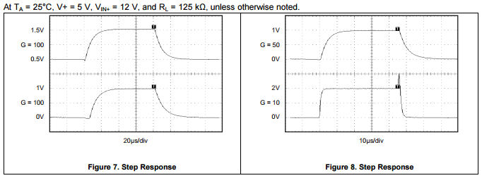
Just another quick note, I did check both Vsns and Vbuf outputs.


The positive step response is measured at 2.96ms and the negative step response is measured at 3.0ms.
Summary
The breakout module is suitable for measuring positive shunt currents at relatively low frequency. The datasheet indicates a faster frequency response than we observed, therefore, it is possible that the specific resistor combinations that were chosen are limiting the frequency somehow. Using the rule-of-thumb:
freq = 0.35/riseTime
It was found that our cutoff frequency is ~116Hz. As a result, I would recommend this module with its current resistor configuration for applications that need performance up to 100Hz.
I Want One!
I have several of these boards. If you want one, just drop me a line and I'm sure that we can work something out for a parts kit or soldered module.
- article
- current-sensor
- curve-tracer
- dispatch
- fan-controller
- fixed-point-math
- load-cell-sensor
- meta
- reference


 RSS
RSS
2
assembly
5
buffer
31
c
3
current sensor
28
curve tracer
2
fan controller
6
fixed-point math
4
interrupt
3
KiCAD
3
labview
5
layout
6
msp430
4
pelican
18
pic24
29
project
12
python
2
Q1.15
4
schematic
10
serial
3
solidworks
2
task manager
2
theme
3
tkinter
9
uart
9
xc16