-
 Fan Controller Progress Update - July
- Date Thu 21 July 2016
- By Jason Jones
- Category fan-controller
- Tags fan-controller project fan controller c layout
Hardware
Hardware was received and built up quickly in the past couple of days. In fact, all has progressed more quickly that I initially imagined. Osh Park - those loveable guys - bumped my order up to the 'premium' panel, so I received the boards a week earlier than anticipated!
Rework
That isn't to say that there haven't been a couple of bumps along the road. Once again, I apparently missed the capacitor pin on the microcontroller and assigned it to a function. This required two reworks: (1) the addition of a capacitor and (2) moving of a sense trace to a different pin. Additionally, I misread pin 14 on the microcontroller and thought that it was one of the PWM outputs that I could use. Unfortunately, that particular PWM module was already being utilized, so I had to move the PWM function for fan 3 to pin 18.
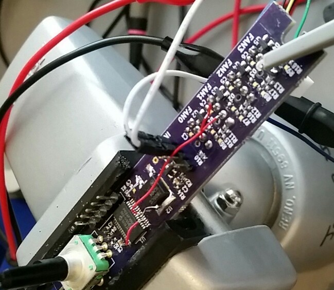
You can see that I soldered a small capacitor to the back of U2 (the DPAK) and soldered a lead to the Vcap pin of the microcontroller. You can also see pin 18 being shunted to pin 14 and replacement of one of the tachometer signal traces. This rework job was minor and took just a few minutes to do, so I am happy with the results.
Hardware Functionality
As the firmware has progressed, the functionality of several of the hardware blocks has been tested as well. We have verified the functionality of the following bits of hardware:
- PWM modules
- PWM outputs
- TACH inputs
- PWM input
- TACH output
- Rotary encoder/switch
In addition, it was nice to hook up the programmer and have it simply work right off the bat. I hadn't even cleaned flux off the board before I was flashing the microcontroller.
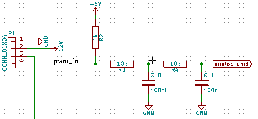
PWM Input
The only real issue that I had as I went through the firmware buildup involved measuring the input pulses of PWM. The microcontroller - a PIC24FV16KM202 - has 5 modules which can be configured as PWM, input capture, or general-purpose timer. I am already using all 5 of these for PWM and timer, so I decided that it would actually be better to convert the input PWM to an analog signal using an RC circuit. We will implement this on v1.1 of the hardware.
Part Flexibility
I also decided that it would be a good idea to make the schematic/layout compatible with the 3.3V part in case I ran into part compatibility issues down the road. As a result, several I/O were moved around a bit in order to accomplish this goal.
Firmware
The firmware has been a bit more complex than I had initially thought it would be. Isn't that always the case, though? The idea is to easily maintain control of the fans but to also have the fans pulling minimal power at all times.
I'm still trying to decide if I should implement some sort of protection feature into the board. Fans are supposed to have integrated protections against locked rotor and other similar types of failures, so I don't know how much effort I should put into protection. Hit me in the comments if you have an opinion.
Again, a reminder of the state machine from the last article:

We will bounce through some of the functionality of the firmware for the user, but the complete source is on github.
Encoder
The code for the encoder was a bit more difficult that I had anticipated. My hacked-together code didn't really work very well and I did a quick search and found a really good article - with sample code - that worked quite well after a bit of adaptation.
1 2 3 4 5 6 7 8 9 10 11 12 13 14 15 16 17 18 19 | void serviceEncoder(void){
static int8_t enc_states[] = {0,-1,1,0,1,0,0,-1,-1,0,0,1,0,1,-1,0};
static uint8_t old_AB = 0;
old_AB <<= 2;
old_AB |= (uint8_t)(PORTA & 0x0003);
int8_t state = enc_states[(old_AB & 0x0f)];
if(state == 1){
/* counter-clockwise */
lastEncoderTime = TASK_getTime();
encoderTurned--; // reverse the direction of CW and CCW
}else if(state == -1){
/* clockwise */
lastEncoderTime = TASK_getTime();
encoderTurned++; // reverse the direction of CW and CCW
}
}
|
I decided to poll this function as a task every 1ms rather than use interrupts. This is mainly because the encoder is relatively low priority and I don't want to potentially delay a different interrupt that may be more time-critical.
After user adjustments are made to the fan speed, the fan will wait 5s from the lastEncoderTime before saving the
values and returning to the normal state.
Periodically, encoderTurned is polled by a different function which determines how far the encoder has been turned
since the last read. This allows the higher level of software to have a crude sense of the speed of rotation of the
encoder, which turns out to be quite useful. We are using this knowledge to implement two modes of PWM adjustment, fine
and course adjustment. If |encoderTurned| is greater than some value, then we will add more adjustment. The user
will likely not even know the two modes since it is very natural to turn the knob quickly for large adjustments and
slowly for fine adjustments.
EEPROM
Working with EEPROM within the Microchip products is simple, but always requires a bit of tinkering on my part to get it into an easily workable solution.
I implemented three functions to assist me in writing to any address within the EEPROM:
void EEPROM_erase(uint16_t address);
void EEPROM_write(uint16_t address, uint16_t value);
uint16_t EEPROM_read(uint16_t address);
The 'gotchas':
- Microchip on-chip EEPROMs are 16-bits wide and the address must be even so that you are addressing the lower byte. Even addresses will simply not write.
- Memory must be erased before it can be written - erase first!
- Wait for
NVMCONbits.WRto be cleared before continuing. If you don't, and you try another erase or write before it has cleared, you will be sorry. Don't be sorry. Just plan to wait the proper time.
My code is full of Microchip special functions that come with the XC16 environment. I wrote the core part of these functions
using Microchip example code with only slight modification to suit my purposes. An example using the EEPROM_write
function:
1 2 3 4 5 6 7 8 9 10 11 12 13 14 15 16 | uint16_t __attribute__((space(eedata))) eedata[__EEDATA_LENGTH >> 1];
void EEPROM_write(uint16_t address, uint16_t value){
EEPROM_erase(address);
NVMCON = 0x4004;
/* Set up a pointer to the EEPROM location to be written */
TBLPAG = __builtin_tblpage(eedata);
uint16_t offset = __builtin_tbloffset(eedata) + (address << 1);
__builtin_tblwtl(offset, value);
asm volatile ("disi #5");
__builtin_write_NVM();
while(NVMCONbits.WR == 1); // wait for write sequence to complete
}
|
Before writing any functions, we declare an array eedata which represents all of the EEPROM memory as an array. The
__EEDATA_LENGTH is a device header file define and is in bytes, so we have translated that into 16-bit values with
the declaration. As a result, we need to halve the __EEDATA_LENGTH or we will have a compiler memory allocation error.
Within the function, the first thing we do is erase the address before trying to write to it. Erasing sets all of the bits
of an address to 1, since we can only actually write 0 values.
Next, we setup NVMCON appropriately to perform a write sequence. Consult the datasheet if you want more information. There are different values required for read, erase, and write operations.
We set the 'page' and 'offset', which are really just a memory location. Microchip using paging - which can be very confusing - but they do provide example code. Note that this is also where we add our address offset. If we write to location 0, then these functions will write to the first location available in EEPROM memory. If we write to location 1, then the write will take place in the second location, and so on...
There is an assembly unlock sequence that must occur in order to write to the EEPROM. This unlock sequence is contained within
__builtin_write_NVM();, but the sequence itself must not be interrupted, so we execute a disi #5 assembly instruction, or
'disable instructions for 5 cycles'.
Once the write is initiated, we simply wait for the write bit to clear before proceeding. In some applications, the 4ms of write time might be intolerable (think motor control), but our application has plenty of time to allow for a 4ms delay, so we have no special considerations.
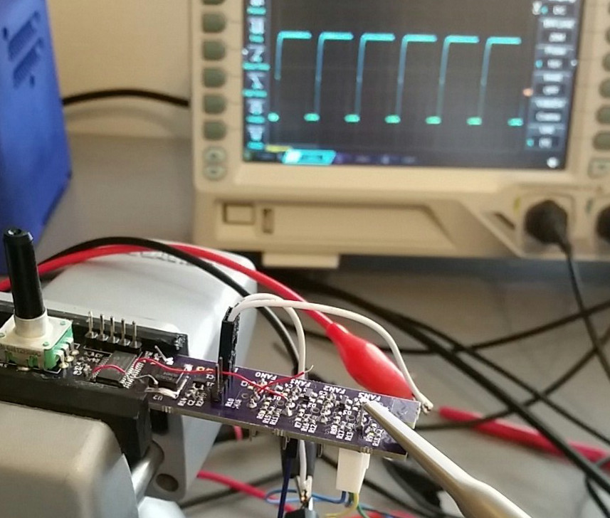
Measuring Input PWM
Measuring the input PWM command is a priority. Initially, I setup a couple of change notification interrupts, measured the input pulse duration and period, and calculated a duty cycles. This worked fine for the middling values of PWM, but doesn't work at all for 0% or 100% duty cycle since the change notice - by definition - requires a change in the pin state. After fiddling with the logic for a bit, I decided that measuring the pulse width is not the best way to solve this problem. Converting the PWM to an analog value is trivial in hardware and performs the logic required perfectly.
- When at 0% PWM, then the analog signal is 0V.
- When at 100% PWM, then the analog signal is 5V.
- When the input is disconnected, the analog signal is 5V.
What more could you ask for?
Tach Output
Ultimately, one has to decide how to route the tach for four fans into one output. I decided that I would go for the simplest option and simply route the tach input for Fan 0 to the tach output to the motherboard. To do this, I set up a change notification interrupt that will read the tach input pin and reflect that on the output. It works perfectly.
Next Version
The version tested was v1.0 and the next version will be v1.1. I made a couple of decisions:
- It wouldn't be difficult to make the schematic compatible with the 3.3V drop-in replacement for this device, so v1.1 will be able to use the 5V chip or the 3.3V chip with the same code. This requires moving a few pin functions around, but not much.
- Change the form factor to something more conventional - I went with the 60mm x 37mm Sick of Beige form... because I like it.
- Use the RC circuit to change PWM to an analog signal.
The layout turned out well, but used a bit more board space than the last layout:
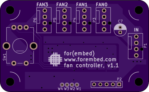
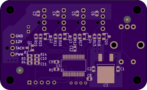
I placed all SMT components on one side of the board and all through-hole components on the other side of the board. I also took a bit of time to label each FAN and the input along with all of the input net names on the SMT side of the board. This was mainly in case I found myself soldering leads to the board, but also serves as a nice visual aid.
With this nice form factor, I should be able to easily place an acrylic case around my electronics, making it a bit safer to place within a PC.
Future Applications
With this hardware/firmware, it is possible to control four fans with or without a motherboard present. Simply set the maximum speed and go.
I saw one application on Tindie that allows one to scale the output tach in order to fool the motherboard when installing more quiet fans. There is no reason that this same thing couldn't be done with this hardware.
One might also use re-program this as a fail-safe. If one fan stops working, then the next fan is started and the new tach signal is routed appropriately.
These are just a couple of ideas. If you get a couple of ideas, then hit me up in the comments.
- article
- current-sensor
- curve-tracer
- dispatch
- fan-controller
- fixed-point-math
- load-cell-sensor
- meta
- reference


 RSS
RSS
2
assembly
5
buffer
31
c
3
current sensor
28
curve tracer
2
fan controller
6
fixed-point math
4
interrupt
3
KiCAD
3
labview
5
layout
6
msp430
4
pelican
18
pic24
29
project
12
python
2
Q1.15
4
schematic
10
serial
3
solidworks
2
task manager
2
theme
3
tkinter
9
uart
9
xc16