-
 Project Curve Tracer - v1.1 Model
- Date Mon 20 June 2016
- By Jason Jones
- Category curve-tracer
- Tags curve-tracer curve tracer solidworks model cad
Modeling Software
I am a big fan of SolidWorks as a 3D design package. I am completely untrained, yet with a few hours of practice, anyone can pick up the software and do something useful. After a while, you can start to do some really nice things with it!
The biggest down side is the cost. The sticker price for one of these is $4000 (last I checked a few years back). I purchased a copy at a significant discount for a project that I was working on, but I don't pay the maintenance on it, so the software never gets updated.
I have looked into FreeCAD and other tools, but I have found that nothing comes close to SolidWorks where my time is concerned, so I stick with it (for now).
Modeling
I only modeled the connectors. In this case, the resistors and ICs are simply too short to be concerned with. I have had to model components in the past when there was limited headroom in a particular application, but this is not one of those cases.
You may also note that I skipped modeling the hardware as well. I placed the components with plenty of room for english or metric hardware. In english units:
- 4x 4-40 threaded hex standoff, 0.75" long
- 4x 4-40 straight-through standoff, 0.25" long
- 8x 4-40 screw, pan-head, 0.5" long
If you are into metric:
- 4x M3 threaded hex standoff, 20mm long
- 4x M3 straight-through standoff, 6mm long
- 8x M3 screw, pan-head, 12mm long
You should note that this is preliminary and I haven't tested the setup just yet... but I will!
PCB Changes from v1.0 to v1.1
There are no changes to the active components of the schematic, only the interfaces.
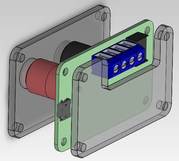
We removed two terminals from the screw terminal row and replaced them with the safety banana jacks. You can now use your existing multimeter leads to interface with the curve tracer! In addition, any other banana jack equipped leads will interface with the curve tracer as well. I feel that it is a safe assumption that anyone that might want one of these would also have a set of multimeter leads laying around. You can see the two large barrel components out of the bottom of the PCBA in the model. I initially wanted to include these on the top layer, but they are simply too large to make this practical, so I moved them to the bottom.
Also, we moved the USB connector from the 'back' to the 'side'. This allows the user to place the curve tracer on its 'back' and have access to all of the terminals without having to re-orient the board.
All-in-all, very minor changes.
Case Design
You may remember that we based the footprint off of the Sick of Beige case design. Specifically, the 'golden rectangle' 60mm x 37mm board. We like this choice, but it has left us with the requirement to cut out a couple of holes and go mildly into case design.

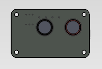
The cutouts are simple and should be quite easy to manage on any laser cutter. I'm considering a couple of places for the case manufacturing, such as Ponoko. First, I have to figure out how to generate vector graphics. If you happen to know a quick and dirty way to get a sketch from SolidWorks into an SVG form, drop a line in the comments!
- article
- current-sensor
- curve-tracer
- dispatch
- fan-controller
- fixed-point-math
- load-cell-sensor
- meta
- reference


 RSS
RSS
2
assembly
5
buffer
31
c
3
current sensor
28
curve tracer
2
fan controller
6
fixed-point math
4
interrupt
3
KiCAD
3
labview
5
layout
6
msp430
4
pelican
18
pic24
29
project
12
python
2
Q1.15
4
schematic
10
serial
3
solidworks
2
task manager
2
theme
3
tkinter
9
uart
9
xc16