-
 Project Curve Tracer - DAC Initialization and Utilization
- Date Tue 23 February 2016
- By Jason Jones
- Category curve-tracer
- Tags curve-tracer c curve tracer pic24 project
Go back to the first post to get some background on this project!
Hardware Patch
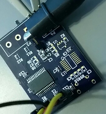
Just a couple of notes before we begin coding. I was using the pinout for the "PIC24F" part on the datasheet whereas I should have been using the "PIC24FJ" part. This will involve a small patch wire, but nothing major. There is supposed to be a capacitor for an on-die voltage regulator. For the moment, populating R8 with a 4.7uF ceramic capacitor and shorting C2 will do the trick.
Additionally, I wasn't paying close attention when I placed the programming header on the schematic and pins 1 and 2 got mixed up. We will fix this in the next layout.
I'll update the schematic when I know what all of the patch wires are going to be :).
Short Term Goals
The first goal will be to simply get the DAC functioning well enough to output a couple of sine waves at reasonable frequencies, maybe in the 1kHz range. That's it, simple enough! The short version is that a timer interrupt will occur which will add 'omega' to 'theta' at periodic intervals. We will adjust 'omega' in order to adjust the frequency.
Libraries
For this application, we are going to use libmathq15, available on github. It has a nice balance of memory usage and accuracy and has been well-tested. It is likely possible that we could do better using a custom lookup table or function, but the testing and overhead - especially at this beginning stage - is not worth the extra hassle.
Compiler Settings
The primary setting that you must enable is optimization level. Go to the settings and setup the compiler to -O1 optimization (maximum 'free' optimization level).
Initialization
Any microcontroller must be initialized, and the PIC24 series is no exception. For the moment, we aren't going to worry about external clock sources, so we will use the configuration #pragma statements to setup the internal FRC with 4x PLL, which will set us up for 16MIPS.
Next, we initialize the DACs through the initLowZAnalogOut() function. Just a few register operations to:
- Set the tri-state (TRISB) and analog-select (ANSB) pins
- Enable the DAC for left-aligned input (our library uses all 16-bits and the DAC only uses 8 bits)
The final initialization involves the timer interrupt. For the moment, we will configure the timer interrupt to fire every 250cycles using PR4. This may end up too low a number, but should give us a good start at a high operating frequency as 250cycles at 16MIPS will result in 15.625us for each sample. Assuming a 24-sample sinusoidal waveform, we will have a period of 375us, which would result in 2.67kHz. This could be better, but isn't bad. At our final instruction frequency of 12MIPS, our max frequency becomes 2kHz.
I won't repeat the source code for this portion here, but you can find it on github.
Generating a Waveform
Now we get to the meat of the entire post, the generation of the sine wave. In order to get a +/- 5V output, we will actually be generating two sine waveforms that are 180 degrees out of phase. We will take our angle, 'theta', add the new offset 'omega', then load DAC1 with the sine of theta and load DAC2 with the sine of 'theta + 180º'. Since this is an interrupt function that takes place periodically, then we will have to clear the interrupt flag.
1 2 3 4 5 6 7 8 9 10 11 | void _ISR _T1Interrupt(void){
static q16angle_t theta = 0;
theta += omega;
DAC1DAT = q15_fast_sin(theta) + 32768;
DAC2DAT = q15_fast_sin(theta + 32768) + 32768; // theta + 180 deg
IFS0bits.T1IF = 0;
return;
}
|
Each waveform has an 'offset' of 32768. This must occur because we cannot generate negative voltages with our DAC. All voltages generated must be positive. Additionally, the second waveform has a +32768 offset to theta. This represents a 180° phase relationship between the two waveforms. This is how we are going to apply both a positive and negative voltage to the device-under-test.
Simulation of the timer interrupt reveals that it takes \~60 cycles to execute the interrupt. This doesn't include the \~10 cycles of context saving and restoring that are performed, so \~70 cycles is a reasonably safe bet. Our period of 250 cycles will probably remain exactly where it is since we have other things to do with the extra cycles.
Evaluation
How does the code perform? Lets take a look at the waveforms!

At 1.3kHz, we can see the high-frequency DAC loads when we look closely, but the waveform appears adequate. We may employ a bit of averaging in order to get the benefit of multiple sequential waveforms, but it doesn't appear that averaging would be necessary.

On the other hand, at 2.7kHz, we can clearly see the stair-stepping caused by the DAC loads. Again, for our application, this could probably be overcome with some averaging techniques, but at some point, we would be interfering with our data.
Our target of 1.0kHz appears to be sufficiently proven to continue with that goal in mind.
What Next?
Next post, we will connect the internal opamp to the DAC in the voltage follower configuration. This will translate the relatively high impedance DAC voltage into a much lower impedance, which is what we desire for signal integrity. Stay close!
- article
- current-sensor
- curve-tracer
- dispatch
- fan-controller
- fixed-point-math
- load-cell-sensor
- meta
- reference


 RSS
RSS
2
assembly
5
buffer
31
c
3
current sensor
28
curve tracer
2
fan controller
6
fixed-point math
4
interrupt
3
KiCAD
3
labview
5
layout
6
msp430
4
pelican
18
pic24
29
project
12
python
2
Q1.15
4
schematic
10
serial
3
solidworks
2
task manager
2
theme
3
tkinter
9
uart
9
xc16