-
 Project Curve Tracer - Schematic Part Selection
- Date Tue 09 February 2016
- By Jason Jones
- Category curve-tracer
- Tags curve-tracer curve tracer pic24 project schematic
You may want to go back to Project Curve Tracer - Requirements in order to gain some background on this project.
Shield or Custom?
After thinking about this for a bit, I decided to go against making this a shield for the MSP430 launchpad or Arduino. This decision is primarily based on cost. Even the cheapest launchpad - which probably wouldn't fulfill my requirements - is $10, which is most of my $15 budget. Not to mention that the board size to fit over the Launchpad or Arduino is large enough to eat most - if not all - of my budget as well.
I/O Requirements
We visited the high-level requirements in the last post. Here, we need to get down into IC requirements. The ideal single-chip solution would have:
- 2-4 Digital-to-Analog Converters (DACs)
- 2-4 PWM outputs - 10-bit minumum
- 2-4 On-die opamps
- 1 USB peripheral
- 4-8 Analog-to-Digital Converters (ADCs) - 10-bit minumum
- Less than $2.00/part
- Up to 5V operation
- Be very small but solderable - we don't want to pay for board space that we won't use, but we also can't hand-solder BGAs.
So, in order to get a Vpp = 5V, the module must have two analog outputs with complimentary sine waves. This will place a full +5V across the part at the positive peak and a full -5V across the part at the negative peak. This is what the DACs and PWMs would be used for. DACs are preferred.
Two of the opamps are basically buffer amplifiers taking the DAC signal into the input and providing a low-impedance output signal. A typical voltage-follower circuit should do nicely. One of the opamps must be able to amplify a small voltage across a current-sense resistor, so there are at least 3 opamps required in the design. If one or two are on-die, then that would help a great deal.
The USB peripheral is optional. I know as much as the next guy about USB - which isn't much - so I'm leaning toward using an FTDI chip for this portion of the project anyway. We will call this 'optional'.
ADCs are a must. We must be able to read the voltage at the load - high-side and low-side - and also read the current through the load. Ideally, this would occur using a simultaneously sampled A/D, but that isn't very likely. We must be sure that these three samples are read within - say - 1/100th of the waveform? This is somewhat arbitrary, but needs to be taken into account. If our waveform max frequency is 500Hz, then the period is 2ms. If we are to sample in 1/100th of 2ms, then that leads us to having at least 3 samples in 20us, which is one sample for every 6.7us. Taking the inverse of 6.7us gives us a minimum sampling frequency of 150kHz. Since this value is somewhat arbitrarily chosen, we will consider it flexible, but it is good to have an idea of where we want to be. If we run across an A/D that can sample at 100kHz, that would probably do. If we run into one that can sample at 10kHz, then it simply will not do.
MicroController Selection
This leaves me looking around at manufacturer data sheets. I went through several and I believe that I found a great candidate for my project, the PIC24F16KM202. Amongst the requirements that mention '2 to 4' peripherals, it has 2 of almost all of them. Conspicously lacking is USB, so we will go with the FTDI chip with UART. Amongst the features we are interested in:
- 2 DACs (8-bit)
- 4+ PWMs - up to 16 bit
- 2 Opamps - code configurable as voltage followers with the DACs as inputs
- Up to 5V operation
- Several 12-bit A/D inputs at 100ksps, but can go slightly higher for 10-bit A/D results
- 2 UART modules
- $2.50/pc
To ensure that the microcontroller is a good choice for the application, I like to go through the datasheet with a spreadsheet and associate each function with a pin. It always seems like I miss something or that the final schematic doesn't quite agree with my initial pin assignments, but this is a great tool for development.
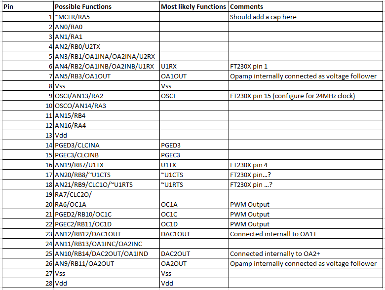
The only thing that is certain is that this will change somewhat, but it is a great start.
External OpAmp
With all of this put together, we only need purchase a single additional opamp. Since the requirement for this opamp is not a tight one, it is desireable to purchase a cheap opamp that has a common footprint. Again, small is essential. The MCP6001 in the SOT-23-5 is a pretty good first approximation. I have used this opamp before and have been happy with its overall performance in a higher-frequency application. It should do just fine as our current amplifier. It will be placed in the differential mode so that it can amplify positive and negative currents through the sense resistor. We will use one of the PWM outputs as the reference so that we can adjust the reference as required by the application in real time.
USB Interface
Finally, the last major component is the USB interface in the form of an FTDI chip. The FT230X meets all of our requirements and has a precision trimmed output pin option which will give the microcontroller a good oscillator without having to purchase a crystal. This comes at the cost of a few MIPS, from 16 to 12 MIPS. At this time, it is believed that this will be adequate for the application. This part comes in at ~$2.38. This is more than we would like, but probably worth it for the moment in order to move forward with our application.
Misc Parts
There remains a slew of resistors, capacitors, and connectors to choose as well. I won't bore you with the selection process of each resistor or connector, but any PWM outputs must have RC filters, amplifiers have resistors, all components have bypass caps. With two SSOP style packages and one SOT-23-5 package along with a USB connector, this board should be smaller than 1.5" x 1.5". That really helps, going a long way towards keeping our boards under the target $15.
Wrapping Up
This post has gone longer than I anticipated, so I will wait until next time to flesh out the actual schematic.
- article
- current-sensor
- curve-tracer
- dispatch
- fan-controller
- fixed-point-math
- load-cell-sensor
- meta
- reference


 RSS
RSS
2
assembly
5
buffer
31
c
3
current sensor
28
curve tracer
2
fan controller
6
fixed-point math
4
interrupt
3
KiCAD
3
labview
5
layout
6
msp430
4
pelican
18
pic24
29
project
12
python
2
Q1.15
4
schematic
10
serial
3
solidworks
2
task manager
2
theme
3
tkinter
9
uart
9
xc16