-
 SolidWorks to Inkscape for Laser Cutting
- Date Thu 23 June 2016
- By Jason Jones
- Category article
- Tags article solidworks inkscape ponoko laser cutting

Intro
In this article, I am going to guide you through an easy way to transfer your SolidWorks design into Inkscape in preparation for laser cutting. There is already some information out there, but the guides appear incomplete, so I'm tossing in my $0.02.
This will not be a SolidWorks or Inkscape tutorial.
We are taking advantage of the fact that SolidWorks will export a dimensionally correct Adobe Illustrator file from a SolidWorks drawing and Inkscape will import this file perfectly. There are other ways to do this! I spent several hours trying to do the same sort of operation using DXF files, but I had to do a lot of cleanup and other manipulation within Inkscape, which was frustrating.
Laser Cutting Service
We will be using Ponoko as our laser cutting service. They are cheap, have several guides online, and - aside from generatign the inkscape files - there is only a modest learning curve, mostly dealing with material selection.
One think that you should know is that, when you are using a service, you are purchasing an entire sheet. Knowing the sheet dimensions is important and Ponoko supplies design templates for Inkscape. We are going to use the "P1" size, which is 180mm x 180mm. This is the smallest sheet, which is appropriate for our initial prototype. Larger sheets will be cheaper per piece, but more expensive up-front.
Sheet Design in SolidWorks
You may have experience with Inkscape, GIMP, or other graphics packages. Image manipulation packages are designed to manipulate pixels. CAD packages are design to manipulate cohesive models. This difference in design philosophy makes designing a sheet in Inkscape difficult and error-prone. CAD packages will do the heavy lifting for you with very little effort, so you will do nearly all of the design work within SolidWorks.
Designing your Parts
Design your parts normally in SolidWorks! Try to keep in mind that you will be laying the parts out in 2D later, so shapes that naturally mate (such as chamfers) will be lower cost than shapes that don't naturally mate so well.
Here, we have two designs that we would like to place on the same sheet. We will call these the case 'top' and 'bottom':
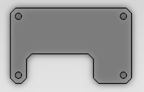
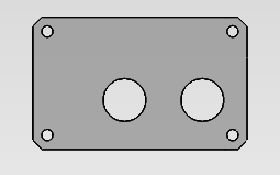
I just grabbed a couple of screenshots. The case top and bottom are actually of the same dimension - 60mm x 37mm - but the pics don't show that clearly.
Layout Out the Sheet
First, take note of your sheet size! You must stay within that sheet size or your design will not be manufacturable!
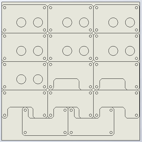
In SolidWorks, 'File -> Make Assembly from Part' to create an assembly. Use mates to place all of your parts on a single layer and - where possible - join the parts so that a single cut is along a straight line of two parts. You can space the parts out and make two cuts of it, but a single cut will reduce your making costs by half.

A couple of tips that you see implemented above.
- Wherever possible, join two straight edges! One cut is half of the price of two.
- Prefer chamfers over fillets. Rounded features slow the cutter down significantly. We have a combination of round and chamfered features.
- Nest parts wherever possible. You can see that we have nested the bottom two rows in order to fit a couple more designs onto the board. If you can slightly change your design to take advantage of nesting, do it! You are paying for a complete sheet of material and you should use as much of it as you can!
Create a SolidWorks Drawing
You can do an Adobe Illustrator export from here, but it won't work correctly. You need to create a Solidworks Drawing using 'File->Make Drawing from Assembly'.
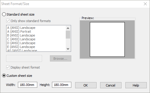
When you create the new drawing, us the 'custom sheet size'. You want the drawing to be blank - no title block! What you see will be exported.

'View Layout' tab, then 'Model View'. Once you are in the 'Model View', be sure to select the custom scale and select 1:1.
Export from SolidWorks
'File->Save As...' and be sure to select the file format as "Adobe Illustrator Files (*.ai)".
Import Inkscape
Download Templates
If you downloaded the templates, great! If you didn't, go get them! We will be opening the "P1 Inkscape.svg" file and saving it as something else.
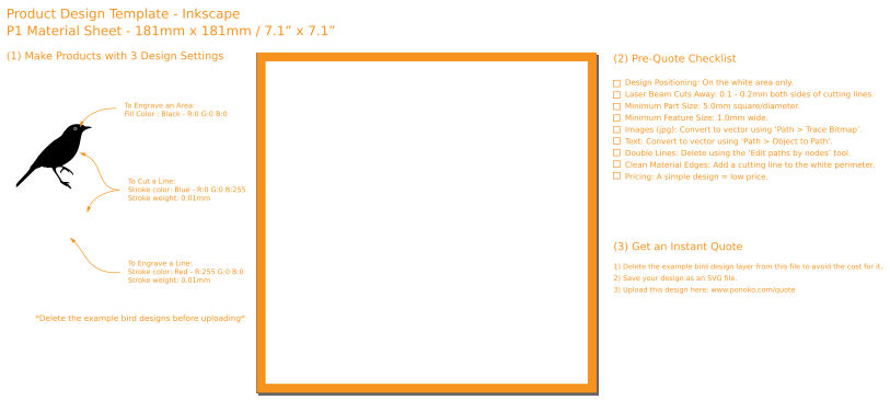
The file contains a lot of information. We will not be engraving, but know that if you need to engrave, you will use 'red' or 'black'. We will be cutting, so we will use 'blue'. Red is for engraved lines, black is for engraved areas, blue is for cuts.
Importing
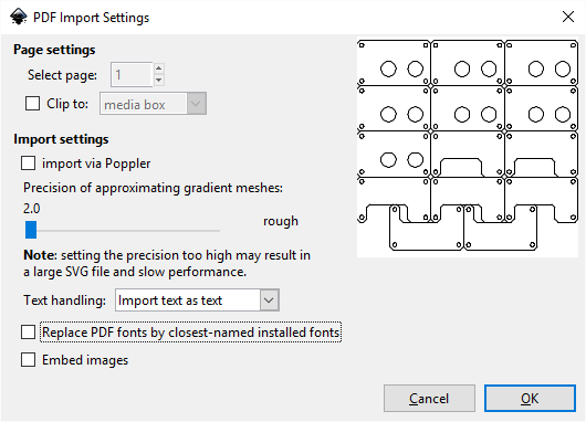
'File->Import...' and navigate to the *.ai file that you saved from SolidWorks. I like to uncheck the lower two boxes.
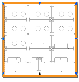
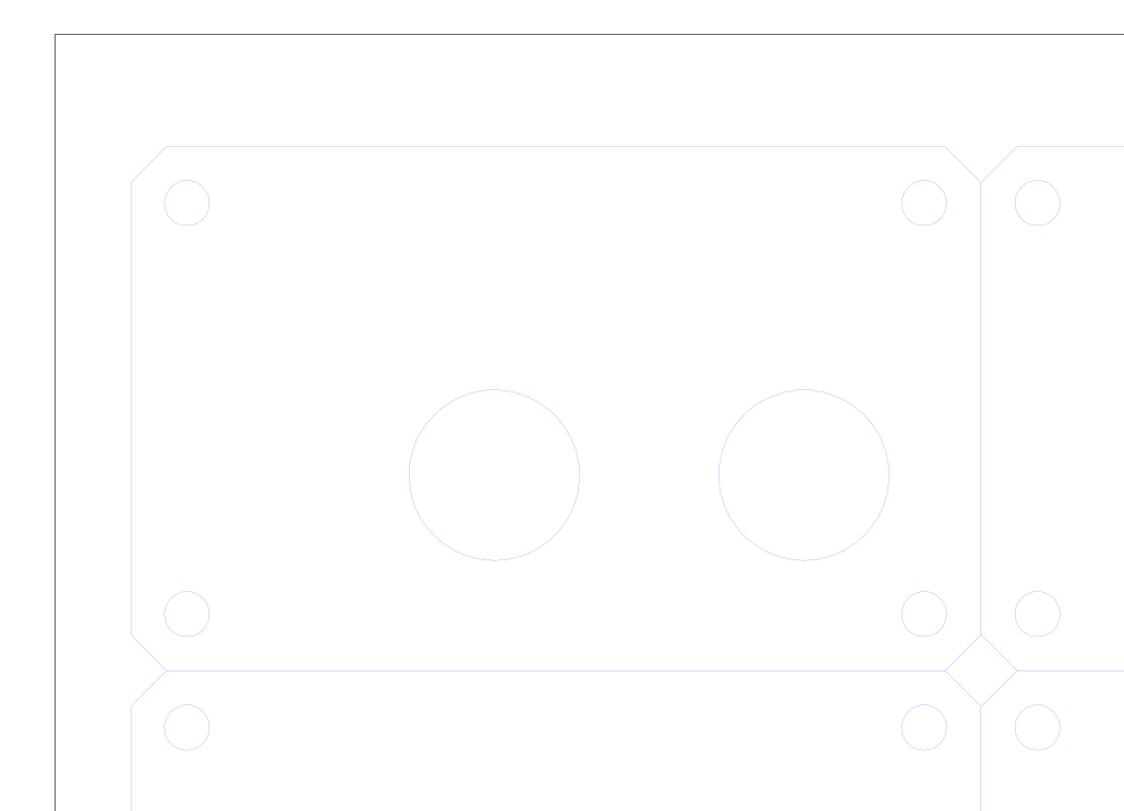
Now you should have a drawing that looks pretty similar to the drawing that you created in SolidWorks. Use the cursor to center the entire panel on the P1 panel, staying within the orange template. DO NOT grab the little arrows! They will drag only that node and distort your panel! If you accidently grap one of these and drag, be sure to undo it or simply re-import.
Create Paths
You might imagine that the laser tool head must travel and have a path to travel along. With your import selected, go to 'Path->Object to Path'. This doesn't appear to change much, but it does change the underlying format with which the file objects are saved.
The Right Strokes
To the right, there is a menu that may be minimized called "Fill and Stroke". Clik on it so that you can see the "Fill", "Stroke Paint", and "Stroke Style" tabs.
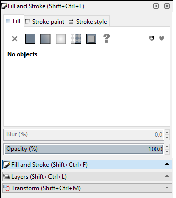
Click the "Fill" tab and click on the "X". There should be no fill for the cutting outlines.
Click the "Stroke Paint" tab. Click "Flat color" just next to the "X", with color mode "RGB" and the values should be 0, 0, 255, 255. This defines "blue", which is the cutting color. If you wanted to engrave, you would use red or black.
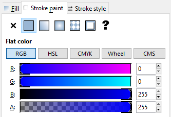
Finally, click on the "Stroke style" tab. The width should be set to 0.01mm, according to the Ponoko documentation.
Once you do all of this, your design has a very thin line, you may not even be able to see it! Zoom in (CTRL + mouse wheel) to see the thin line.
Engraving
In some cases, you may wish to add an engraving to your item(s). I would suggest that you create the engraving and convert it to a path in a separate Inkscape window, then copy/paste it into this window. There are lots of ways to do it, but I have had the most success using that method.
Finishing Up
Before uploading your design, remove unnecessary layers using the layers dialog (usually to the right). Right-click on each layer that is not called "Your Design" and remove it.
Now save your file in the default *.svg format and upload to Ponoko!
- article
- current-sensor
- curve-tracer
- dispatch
- fan-controller
- fixed-point-math
- load-cell-sensor
- meta
- reference


 RSS
RSS
2
assembly
5
buffer
31
c
3
current sensor
28
curve tracer
2
fan controller
6
fixed-point math
4
interrupt
3
KiCAD
3
labview
5
layout
6
msp430
4
pelican
18
pic24
29
project
12
python
2
Q1.15
4
schematic
10
serial
3
solidworks
2
task manager
2
theme
3
tkinter
9
uart
9
xc16