-
 Current Sensor Datasheet
- Date Tue 29 March 2016
- By Jason Jones
- Category reference
- Tags reference current sensor project datasheet
Purpose
The current sensor breakout is a breadboard compatible breakout module for the INA139 series of high-side current sensor ICs. In addition to providing a mount point for the INA139 part and the shunt resistor, the module also includes a low-impedance output suitable for driving an analog-to-digital converter.
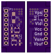
Pinout
The potentially high-current pins - Vps and Vload - have two pins each dedicated to their functionality. It is not necessary to connect both pins.
| Pin Number | Pin Label | Description |
|---|---|---|
| 1 | Vps | Power supply pin 1 - connect to the incoming power supply |
| 2 | Vps | Power supply pin 2 - connect to the incoming power supply |
| 3 | Vload | Load pin 1 - connect to the load |
| 4 | Vload | Load pin 2 - connect to the load |
| 5 | Vcc | Logic-level Voltage Supply |
| 6 | Gnd | Ground Pin |
| 7 | Vsns | Sense voltage pin - leave unconnected in most applications unless filtering is desired |
| 8 | Vbuf | Voltage buffer output - connect this to the ADC or other measurement device |
Ratings
Sustained Ratings
Each part is designed so that no more than 150mV is dropped across the part at the rated current. It is possible to run a multitude of settings on this part, but I have found that the most common combinations are targeted for 3.3V and 5V applications. Below you will find common configurations for measuring currents between 3mA to 3.0A.
| Part Number | Rated Current | Transimpedance | Volts Out @ Irated |
|---|---|---|---|
| ELAS00011100 | 3.0A | 1.65V/A | 4.95V |
| ELAS00011101 | 300mA | 16.5V/A | 4.95V |
| ELAS00011102 | 30mA | 155.1V/A | 4.95V |
| ELAS00011103 | 3mA | 1551V/A | 4.95V |
| ELAS00011104 | 3.0A | 1.1V/A | 3.3V |
| ELAS00011105 | 300mA | 11V/A | 3.3V |
| ELAS00011106 | 30mA | 103.4V/A | 3.3V |
| ELAS00011107 | 3mA | 1034V/A | 3.3V |
Common
These values are common to all part variants.
| Parameter | Value |
|---|---|
| Frequency | 200kHz |
| Accuracy | 2% |
| Recommended Minimum Vcc | 3.0V |
| Recommended Maximum Vcc | 5.0V |
| Recommended Minimum Vps | 3.0V |
| Recommended Maximum Vps | 35.0V |
Absolute Maximum Ratings
| Parameter | Maximum |
|---|---|
| Vps to GND | 40.0V |
| Vcc | 5.5V |
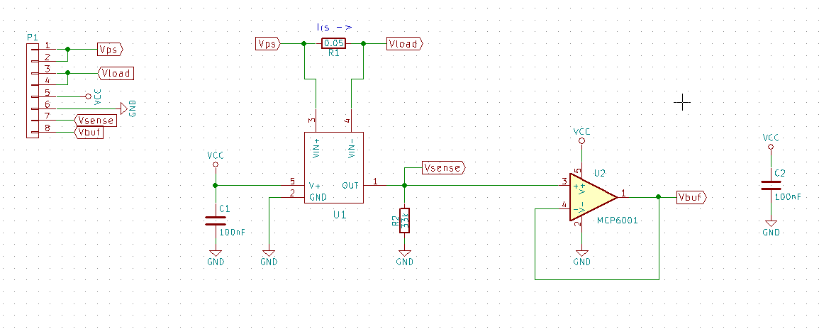
Schematic
The schematic has three sections:
- Shunt Resistor
- High-Side Amplifier
- Voltage Follower
The shunt resistor is the resistor through which all current flows in order to create a differential voltage.
The high-side amplifier circuit is the circuit which measures the differential voltage across the shunt resistor and amplifies the signal to a more easily measured value.
The voltage follower takes the high-impedance output of the high-side amplifier and outputs a low-impedance voltage suitable for driving a multitude of input types, such as analog-to-digital converters.
Connection Diagrams
De-coupling capacitors are not necessary as they are integrated next to the part, although extra capacitance on the inputs of the pins would not compromise the performance of the part in any way.
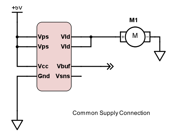
Common Supply
In application in which the Vps is between 3.0V and 5.0V, Vcc and Vps may be connected. This is the simplest method of connection. It is possible that this method of connection may induce noise on the Vcc pin, depending on the load noise characteristics.
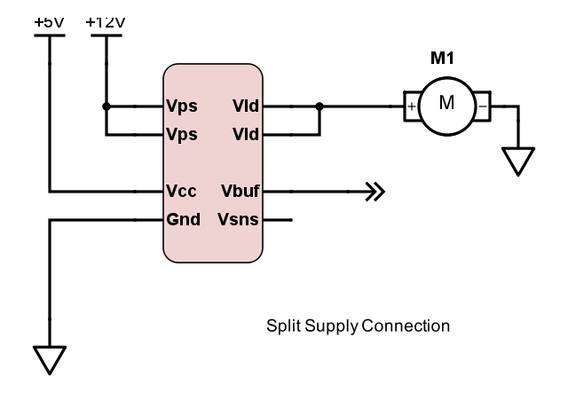
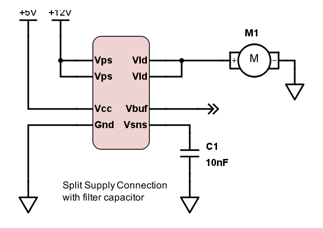
Split Supply
In application in which the Vps is to operate above 5.0V, Vcc should be supplied with its own voltage source between 3.0V and 5.0V.
Filtered
In some situations, it may be desireable to filter the output waveform, reducing the frequency content of the output signal while increasing the 'averaging' effect. When this is desired, a capacitor may be populated between Vsense and GND.
- article
- current-sensor
- curve-tracer
- dispatch
- fan-controller
- fixed-point-math
- load-cell-sensor
- meta
- reference


 RSS
RSS
2
assembly
5
buffer
31
c
3
current sensor
28
curve tracer
2
fan controller
6
fixed-point math
4
interrupt
3
KiCAD
3
labview
5
layout
6
msp430
4
pelican
18
pic24
29
project
12
python
2
Q1.15
4
schematic
10
serial
3
solidworks
2
task manager
2
theme
3
tkinter
9
uart
9
xc16