-
 Project Curve Tracer - Requirements
- Date Mon 08 February 2016
- By Jason Jones
- Category curve-tracer
- Tags curve-tracer curve tracer huntron tracker 2000
Intro
My first job out of school was as an engineering technician repairing medium to large UPS systems. I only worked there for 6 months, but I learned a lot about the 'real world' and about how to troubleshoot circuits. In my time there, I encountered a piece of equipment called a Huntron Tracker 2000. At first, I was dubious, but after just a short time I could often find the problem with a circuit in seconds using this marvelous device.
What is a Huntron Tracker 2000? It is a curve tracer. The Tracker outputs a sinusoidal (or other, based on settings) waveform and plots voltage on the horizontal axis and current on the vertical axis. This sounds cryptic, but look at a typical VI curve for a diode:
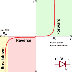
When looking at a typical diode, you would see exactly this curve. A dead short appears as a vertical line (low voltage, high current), an open appears as a horizontal line (high voltage, low current) and so on. Capacitors and inductors have reactance, so they tend to draw ellipses based on the frequency.
At any rate, a Huntron Tracker 2000 costs a few hundred dollars. I believe that - with the right design - one could get 90% of the functionality of a Tracker for less than $15, which brings us to our project: to build a curve tracer for less than $15.
Requirements
I have thought about this a lot recently and - in order to get the cost down - the unit must have a cheap or available power supply and must coopt the screen for another device. The first and easiest thing that comes to mind is to simply use USB for the power supply and use your PC screen as the screen. This is the direction that we will go for the moment in order to keep things simple. Up to this point, we have a screen and power supply without even starting the design.
This brings us to our first real limitation, which is that we will have access to a 5V power supply whereas the Tracker can go up to +/-20V on a particular waveform. As the majority of troubleshooting is done on the 5V setting anyway, this is an acceptable limitation.
Since we are connecting via USB, it is probably necessary to get a microcontroller with a USB peripheral built-in or to use a simple FTDI chip. This decision is somewhat arbitrary. If the right microcontroller can be found with all of the peripherals except the USB, then the FTDI route is acceptable. If the microcontroller can be found that has integrated DACs and opamps and the USB module, that would be ideal.
The 'nominal' frequency of operation is 60Hz, but the unit must be able to output 'complete' waveforms up to 500Hz. It would be nice if we could get to a higher frequency while maintaining signal integrity.
For the moment, we won't worry too much about the actual connectors used for the probes during the prototype stage. I don't want to get into the trap of not moving forward at all because of getting hung up on a connection point for two weeks. Once the first prototype is working, we can work on the next rev of the electronics.
Planning
Any project must have some sort of plan, and any plan must be broken at some point. Here is the rough outline, which I am certain will not be fully followed:
- Design the schematic, including BOM for major items
- Design the board
- Order parts - samples where possible
- Solder parts together
- Code up the waveform generator
- Test the waveform generator along with ensuring the analog signal integrity
- Code up on-board VI curve generation
- Code up USB communications
- Code up PC graphics with USB comms
So, now that I'm looking at the list, it seems like a good idea to just plan on doing at least one post for each of the design items. I'm sure that you don't want to read about 'ordering the parts' and 'soldering', but most of those points look like pretty decent topics.
I'll be hitting the schematic soon, so take notice! More posts are coming!
- article
- current-sensor
- curve-tracer
- dispatch
- fan-controller
- fixed-point-math
- load-cell-sensor
- meta
- reference


 RSS
RSS
2
assembly
5
buffer
31
c
3
current sensor
28
curve tracer
2
fan controller
6
fixed-point math
4
interrupt
3
KiCAD
3
labview
5
layout
6
msp430
4
pelican
18
pic24
29
project
12
python
2
Q1.15
4
schematic
10
serial
3
solidworks
2
task manager
2
theme
3
tkinter
9
uart
9
xc16